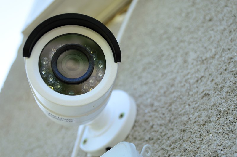
In recent years, advances in cameras and recording devices have allowed a rapid increase in the quality of video surveillance. With surveillance rapidly shifting to IP-based systems, it is important to understand how the quality of recordings impacts the network and storage requirements of a system. Without this understanding, systems may be poorly designed. Insufficient network resources can cause video streams to lose quality or be intermittent. This can also interfere with other applications on the
network. Insufficient processing power on the video recording device will keep it from successfully capturing all of the inbound videos. Insufficient storage results in video retainage timeframes that may not meet business requirements.
How to Design an IP Surveillance System
Fortunately, a few basic facts along with simple math can provide a fairly predictable outcome when designing an IP surveillance system. The reason it is “fairly predictable” instead of a mathematical certainty has to do with the compression that these systems depend on to bring a raw video stream into a manageable amount of data.
A video camera captures a series of static snapshots of what it sees. When viewed in rapid succession, these appear to the human eye as a continuous video stream. The size of each snapshot and the number of snapshots per second combine to determine how much network bandwidth the video will consume on its way to the recording device as well as how much storage will be required for a given length of the video. Of course, these also determine the fidelity reflected in the video of what it represents.
The factors that determine the size of each snapshot (known as the frame size) are resolution and color depth (how accurately colors are recreated). Resolution is measured in horizontal by vertical pixels. A pixel is the smallest visual unit (think “dot”). If you’ve ever looked very closely at lower resolution TVs from the past, or at a magazine photo via a magnifying glass, you know that digital images are comprised of these dots.
Speaking of TV, this provides a great context for describing the visual experience one can expect from various resolutions. Today’s high definition sets present programming at up to 1920×1080 resolution. This is a very clear and high-quality picture. Still, some cameras offer multiples of this resolution, mostly so that recordings can allow you to zoom in on a particular area while maintaining high fidelity.
To determine the “megapixels” of a camera, simply multiply the horizontal by the vertical count of the pixels. This number is usually rounded. So a full high definition camera at 1920×1080 would have 2,073,600 pixels. This is a “2 megapixel” camera. This math is easy.
But things get more complicated with you consider that these cameras compress their images before transmitting them. Most often, they use a compression technology (aka “codec”) called H.264. The main efficiency in the compression technique is derived by the fact that the difference in each frame of a video stream is typically minimal and so the unchanged portions do not have to be broadcast or recorded in full.
So, to determine the bitrate of a camera and corresponding storage requirements, we have to introduce some degree of guesswork. The results will vary depending on the nature of what is being recorded. Is it in constant motion? Are there hours each day when nothing is moving at all?
The basic formula for calculating total bandwidth is:
X * (# of cameras) * (resolution in megapixels of each camera) * (frames per second)
The X factor is dependent on that tricky variable of compressibility, based on what is being viewed. A good but very general value for X in most environments is .25. So, if you have 8 cameras that are full high definition (1920×1080, or 2 megapixels) configured for 15 frames per second, the math would be:
.25 * 8 * 2 * 15 = 60 Megabit/second
But X can be more or less depending on how much activity occurs in the camera’s view and for how much of a given period. Note that in most circumstances, cameras are viewing no activity whatsoever for the majority of any given 24 hour period. The “X factor” of .25 may be much lower in areas where motion is unusual but much higher in areas where motion is non-stop 24×7.
Once you know the total bandwidth that the surveillance system will require, you can select a recording device that has the appropriate processing power to accommodate the system. Most Network Video
Recorders (NVR) will have a published throughput metric. With current systems, this is often several hundred Megabits per second. In large environments, you may need multiple NVRs to handle the
bandwidth.
The network design must also take into account the required throughput. Most local area networks these days are built with 100Meg/second or 1000Meg/second (Gigabit) switches. But be careful with wide-area connections, such as recording over the Internet. There, connection speeds are often much lower. You may also encounter more latency or variability in throughput. Also consider that even if the LAN or WAN can handle the addition of surveillance traffic, it may do so at the expense of impacting
performance of other applications on the network, such as computer data, IP voice traffic, etc.
